In the previous post, I upgraded the drive system of an 800-1 centrifuge, now it’s time for the electronics. A system like this doesn’t require a lot of computing power, so something like an Arduino will be more than enough. However, I’m more of a Raspberry Pi fan, so a Raspberry Pi Pico will do the trick. In fact, there is an even smaller version from Waveshare called the RP2040-Zero.
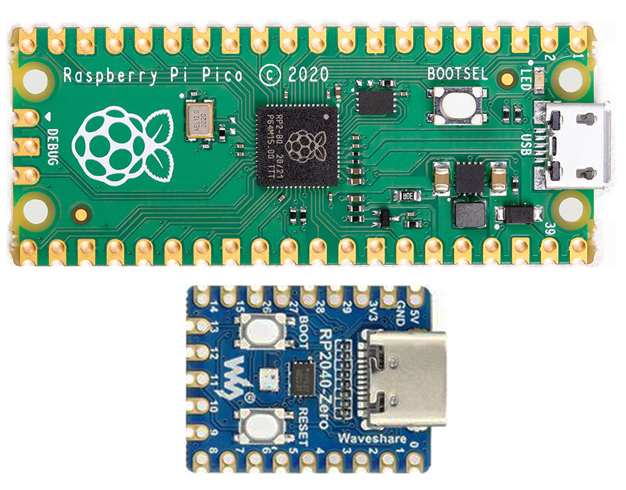
The RP2040 uses the same processor, so it is fully compatible but with a smaller footprint, only 18mm x 23.5mm, and costs less than $7*.
But first, I must determine what is required to ensure enough GPIOs for everything.
- ESC (Motor speed controller) - 1 output
- Rotary encoder (Speed setting) - 3 inputs
- Rotary encoder (Time setting) - 3 inputs
- IR sensor (RPM sensor) - 1 input
- Start button - 1 input
- Status LED - 1 output
- Piezo buzzer - 1 output
- OLED display - 4 outputs
- RPM/RCF switch - 1 output
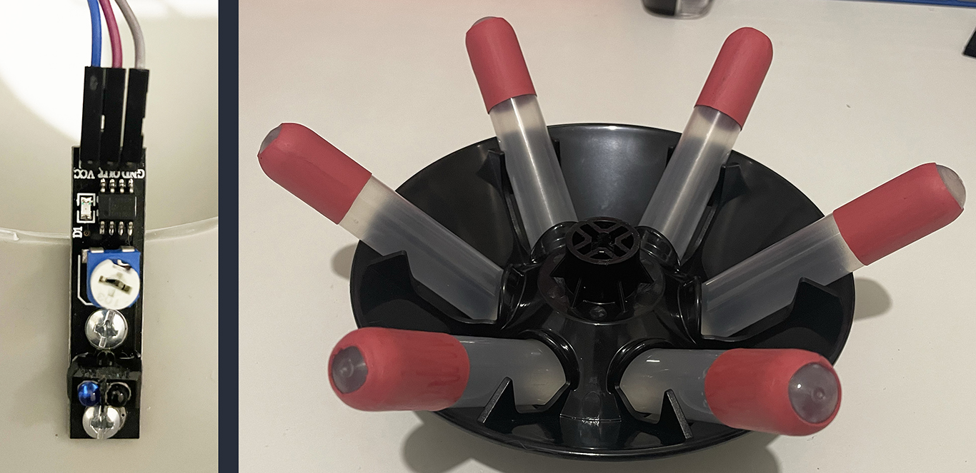
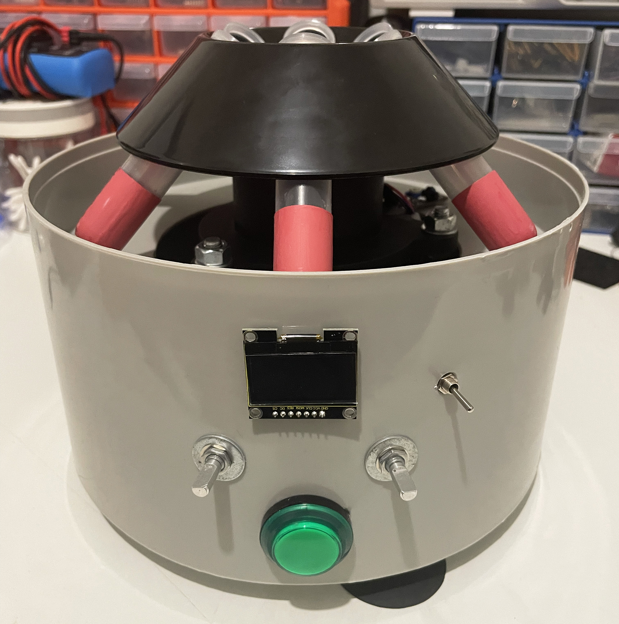
That’s a total of 8 inputs and 4 outputs, so plenty of GPIOs are available. Let’s start with the RPM sensor, an important feature missing from the 800-1. I used the Duinotech Line Tracing Sensor as it works better at short distances than most infrared sensors, mounting it to the ledge under the rotor. I initially thought there would be enough reflectivity from the plastic tube holders, but there wasn’t. So I added reflective tape, but still nothing. Then, I wrapped some red electrical tape around the tubes, which did work, although I didn’t think it would hold on from hours of spinning. Finally, some 20mm red heat shrink tube did the trick. It’s not going anywhere and works a treat!
Time to do some drilling!! There were already the 2 holes from the old dials that I could reuse. One of the old timer mounting holes will be covered by the big Start/Stop button, and the other can be for the RPM/RCF switch. So, all I really had to cut was a hole big enough for the arcade button with a 19mm hole saw and a strip for the display ribbon cable.
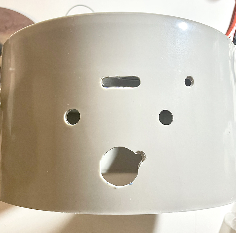
Now, all the hardware is mounted. All the existing holes are filled or covered, so all that is needed is a new label to neaten things up.

To access the RP2040, I drilled a 10mm hole at the back just above the hole for the original power cord. Using a grommet, I glued on a micro-USB to a USB-3 adaptor and plugged in the RP2040. Also added was a 2.1mm barrel jack for the 12v Meanwell GST18A12-P1J power supply, which I’ll be using.
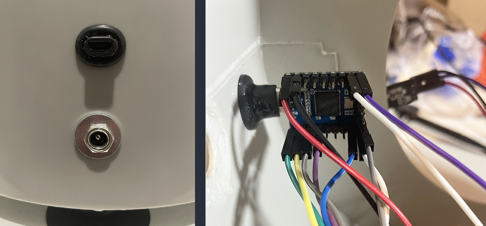
It’s time to wire everything up and make it nice and neat. You may notice the capacitors on the rotary encoders and the button to reduce some of the ringing of the signal during transitions, which causes bouncing.
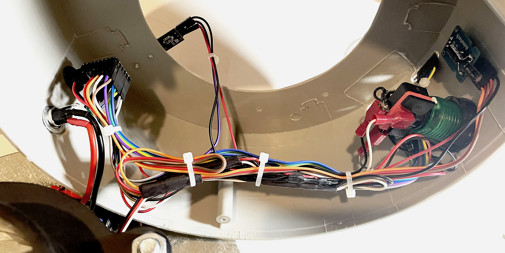
!!One thing to mention, which is REALLY important!!
I’m using the 5v supply from the ESC to power the RP2040 and display, which means if you connect the RP2040 to your computer at the same time the 12v power supply is connected YOU WILL KILL THE RP2040 and maybe the OLED display also. So, you can either make sure the 12v and USB are NOT connected at the same time, or you can use a USB cable with no power. You can make your own powerless USB cable by carefully stripping back the insulation and cutting the power wire, usually the RED one (That’s what works in the movies). Remember, this bit is all on you. Let’s try to keep the smoke on the inside.
With that said, let’s put it all back together and write some software!
Next time, we’ll fire up Thonny and use MicroPython to create our firmware.